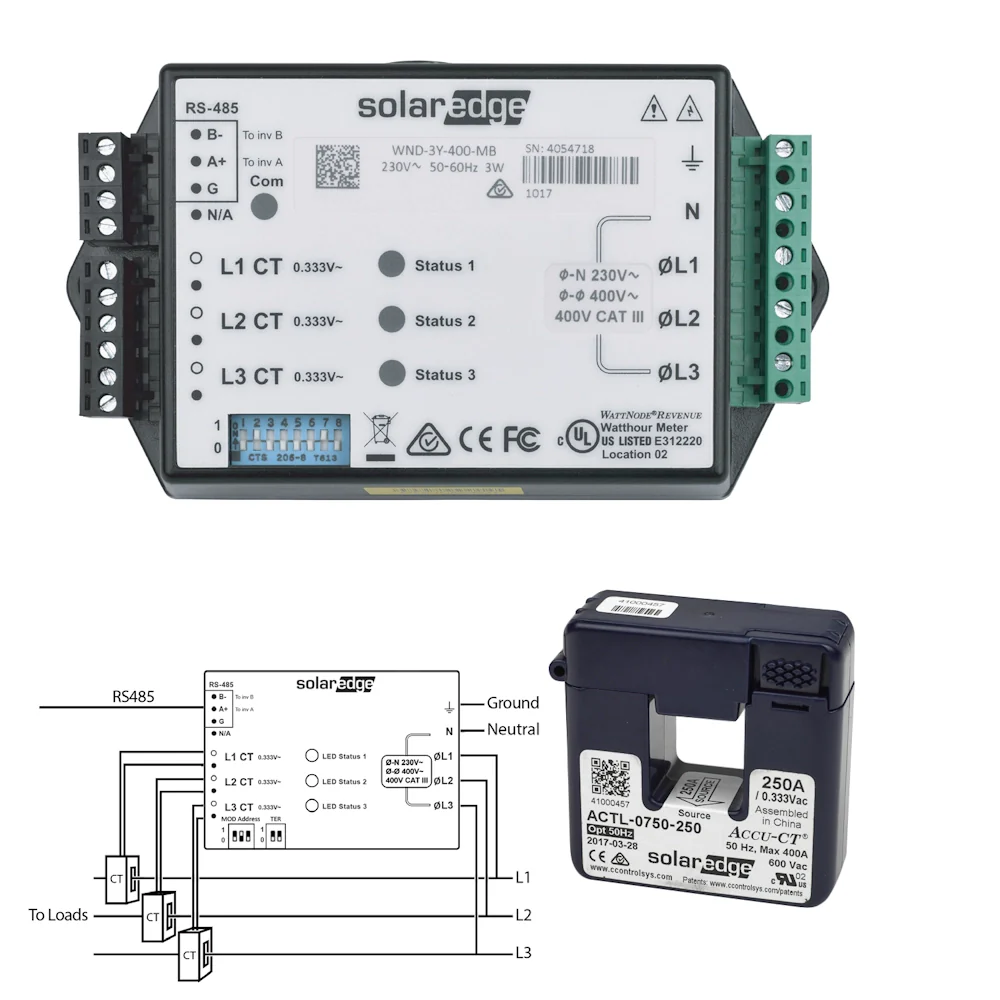
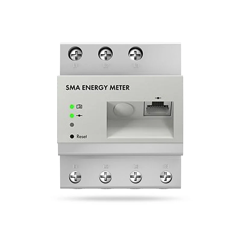
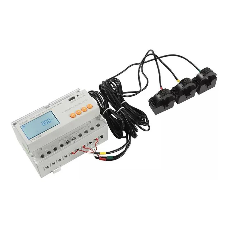
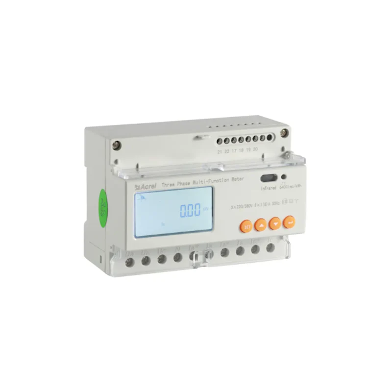
The SolarEdge SE-WND-3Y400-MB-K2 is SolarEdge's dedicated Modbus energy meter for accurate production, consumption, and import/export monitoring in both single-phase and three-phase solar PV installations. It connects to any SolarEdge inverter or Control and Communication Gateway via RS485 Modbus, enabling real-time energy flow data in the SolarEdge monitoring platform. The K2 version is required for export limitation (G100) — it supports Engineering Recommendation G100 Issue 1 Amendment 1 2017 and is the version specified by DNOs for feed-in control in the UK. Compact DIN-rail mounting and a 5-year warranty make it a standard inclusion on any SolarEdge installation.
⚠ Installer Note — Installation must be carried out by a qualified electrician. The meter operates at mains voltage. Always isolate supply before wiring. Current transformers (CTs) are required and sold separately — one CT per phase. Do not apply power until CTs are correctly fitted and CT leads are fully connected.
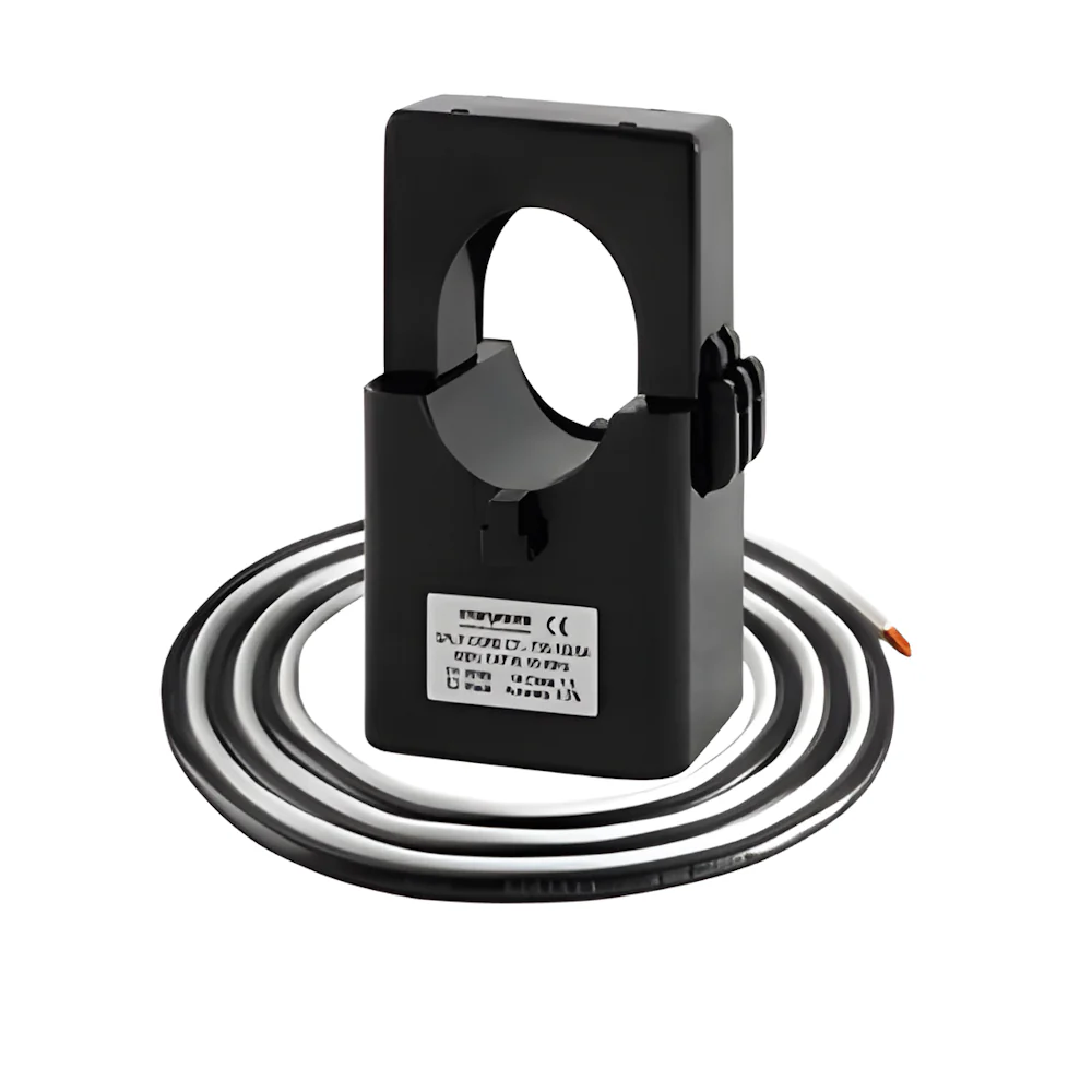
⚡ Compatibility & CT Notice — This meter is compatible with SolarEdge inverters and the SolarEdge Control and Communication Gateway only. It is not compatible with inverters from other manufacturers. Current transformers must be ordered separately — available ratings: 100 A (SECT-SPL-100A-A), 250 A (SECT-SPL-250A-A), and 1000 A (SECT-SPL-1000A-A). Specify K2 on project documentation when export limitation is required.
Technical Specifications
| Manufacturer |
SolarEdge Technologies |
| Part Number |
SE-WND-3Y400-MB-K2 |
| Nominal Voltage — Line to Neutral |
230 Vac |
| Nominal Voltage — Line to Line |
400 Vac |
| Operating Voltage Range |
184–264 Vac (L-N) / 320–460 Vac (L-L) |
| AC Frequency |
48–62 Hz |
| Grids Supported |
Single phase (L / N / PE) & three phase (L1 / L2 / L3 / N / PE) |
| Power Consumption |
1.8 W (typical) |
| Communication Interface |
RS485 Modbus |
| Response Time |
≤ 1 second |
| Default Modbus Device ID |
2 |
| RS485 Line Termination |
120 Ω |
| Accuracy (@ 25°C, PF: 1) |
±1.0% across 1%–100% of rated CT current |
| Dimensions (H × W × D) |
85 × 153 × 38 mm |
| Weight |
310 g |
| Enclosure |
High-impact ABS / ABS-PC plastic, UL 94V-0 / IEC FV-0 |
| Mounting |
DIN rail or wall mount |
| Operating Temperature |
–40°C to +75°C |
| Relative Humidity |
5–90% (non-condensing) |
| Protection Rating |
Indoor; outdoor when installed in a suitable outdoor enclosure |
| Export Limitation Standard |
Engineering Recommendation G100 Issue 1 Amendment 1 2017 (ENA, UK) |
| Safety Standard |
IEC 61010-1 (3rd Edition) |
| Emissions |
FCC Part 15 Class B, CISPR11:2009 Class B |
| Wiring — AC |
1.3–2.0 mm diameter (16–12 AWG), 600 V stranded |
| Wiring — RS485 |
Min. 3-wire shielded twisted pair, 0.2–1 mm² (24–18 AWG); CAT5 acceptable |
| Warranty |
5 years |
Compatible Current Transformers (sold separately — one per phase)
| Model |
Rated RMS Current |
Internal / External Dimensions |
| SECT-SPL-100A-A |
100 A |
16 × 16 mm / 44 × 31 mm |
| SECT-SPL-250A-A |
250 A |
24 × 25 mm / 46.2 × 65.4 mm |
| SECT-SPL-1000A-A |
1000 A |
52 × 52 mm / 120 × 125 mm |
Frequently Asked Questions
Why is the K2 version required for export limitation?
The K2 designation confirms compliance with UK Engineering Recommendation G100 (Issue 1 Amendment 1, 2017), which is the standard that Distribution Network Operators (DNOs) in Great Britain require for active export limitation on solar PV systems. If your DNO has issued a G100 connection agreement with an export limit, you must use the K2 meter. Earlier variants of the WND meter do not carry this certification and will not satisfy DNO requirements.
Where is the meter installed — grid side or inverter side?
For export limitation (G100), the meter must be installed at the grid connection point (i.e. the main incomer, between the grid and the consumer unit / inverter). For consumption monitoring only, it can be installed on the main load circuit. One CT per phase is required — three CTs for a three-phase installation, one CT for single-phase. CT lead length is 2.4 m; if longer RS485 cable runs are needed, use shielded twisted pair over 10 m.
Which CT rating should I choose?
Select the CT based on the maximum rated current of the supply fuse or main incomer at the installation. For residential properties with a 100 A supply, use SECT-SPL-100A-A. For commercial properties with higher demand, use SECT-SPL-250A-A or SECT-SPL-1000A-A accordingly. Always choose the CT that matches or exceeds the maximum expected current — undersizing the CT will cause the reading to clip and may invalidate the G100 compliance.
How does the meter connect to the SolarEdge inverter?
The meter connects via RS485 (Modbus RTU) to the inverter's RS485 port. Wiring is a minimum 3-wire shielded twisted pair (0.2–1 mm²); CAT5 cable is acceptable for runs up to approximately 10 m indoors. For runs over 10 m in areas with lightning risk, external surge protection is recommended. The meter's default Modbus device ID is 2 and the RS485 termination is set to 120 Ω. Multiple meters or inverters can be daisy-chained on the same RS485 bus using the inverter's second RS485 port or a Commercial Gateway.