The Story
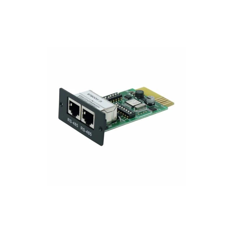
The IC-MODBUS RS-485 Modbus Card is a plug-in communication interface card designed to insert directly into the built-in intelligent slot of compatible Iconica grid-tie hybrid inverters. Once installed, the card establishes an RS-485 Modbus RTU communication link between the inverter and an Eastron SDM630-Modbus V2 energy meter (IC-METER, sold separately). This link is what enables the inverter's self-consumption function — the inverter continuously reads live grid import/export data from the meter and uses it to modulate solar power generation and battery charging, minimising export to the grid and maximising on-site energy use. The card supports both single-inverter and three-inverter parallel system configurations, with DIP-switch addressable Machine IDs (1–247) and configurable communication parameters. It fits Iconica inverters in the 3kW to 10kW range and is a mandatory accessory for any Iconica grid-tie self-consumption installation.
The IC-MODBUS card will only function with compatible Iconica hybrid inverters that include a built-in intelligent expansion slot. It is not compatible with inverters from other manufacturers. Do not attempt installation in a non-Iconica inverter — the card interfaces directly with the inverter's internal communication bus.
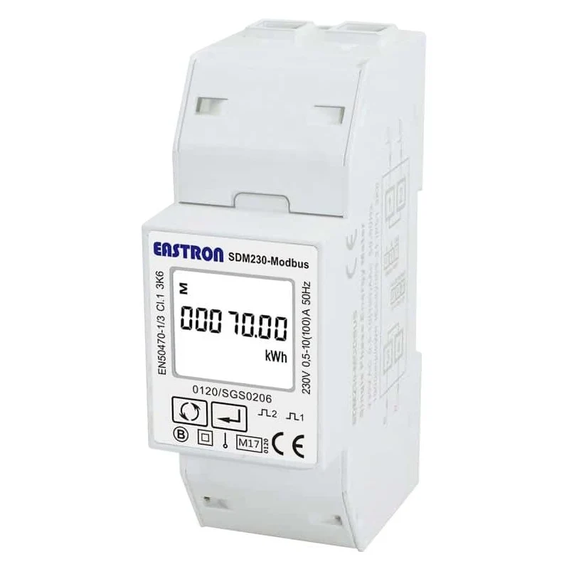
Self-consumption operation requires both the IC-MODBUS card (fitted in the inverter) and the IC-METER Eastron SDM630-Modbus V2 energy meter (installed at the grid connection point). The card alone does not enable self-consumption — the two products must be wired together via RS-485 and configured with matching Modbus parameters.
In a single-inverter system, the card works in single mode (DIP switch bits #1 and #2 both ON). In a three-inverter parallel system, all three cards are set to server mode (both OFF) and assigned unique Modbus IDs (2, 3, and 4 respectively) — the energy meter at address 1 acts as the Modbus master. The inverters must also be set to grid-tie mode with a configured AC-charging window (e.g. 00:00–05:00).
The card slides into the Iconica inverter's intelligent slot via the golden-finger connector — no soldering or internal wiring required. RS-485 wiring (A, B, GND on pins 5, 4, 8 of the RJ45 interface) connects to the energy meter.
8-bit binary DIP switch (SW1) sets the card's Modbus ID (1–247). A full ID-to-switch-position table is provided in the manual. In single-inverter systems, ID is typically set to 1. In three-inverter systems, IDs 2, 3, and 4 are used for the three cards.
Hardware DIP switches set working mode (single/server), parity (even/odd/none + stop bits), and termination resistors (push-up, push-down, terminate). Default configuration: 19200 bps, no parity, 1 stop bit — matching the IC-METER default for immediate pairing.
Once wired and configured, the inverter polls the energy meter in real time and adjusts solar output and battery charge/discharge to keep grid import at or near zero, maximising self-consumption without over-exporting. Grid-Tie with backup mode (priority II) must be selected in the inverter settings.
A single IC-METER energy meter can serve up to three Iconica inverters, each fitted with its own IC-MODBUS card. The Modbus server card acts as the control centre, coordinating power generation and charging across all three inverters from one set of grid measurement data.
On-card push-up, push-down, and termination resistors are individually enabled via DIP switches (#6, #7, #8 respectively — all ON by default). These ensure RS-485 signal integrity over cable runs and can be disabled for long bus configurations with external termination.
| IC-MODBUS RS-485 Modbus Card — Technical Specification (from manufacturer quick guide V1.3) | |
|---|---|
| Communication | |
| Interface | RS-485 Modbus RTU |
| Default Baud Rate | 19200 bps |
| Configurable Baud Rates | Configurable via DIP switch to match energy meter settings |
| Default Parity / Stop Bits | None / 1 |
| Machine ID Range | 1–247 (set via 8-bit DIP switch SW1) |
| RS-485 Pin Assignment (RJ45) | Pin 4 = RS-485-B; Pin 5 = RS-485-A; Pin 8 = GND |
| System Configuration | |
| Working Modes | Single mode (reset total or per-phase feed-in power to zero); Server mode (3-inverter parallel) |
| Max Inverters per Energy Meter | 3 |
| Inverter Setting Required | Grid-Tie with backup (priority II); AC-charging duration configured (e.g. 00:00–05:00) |
| Termination Resistors | Push-up, push-down, terminate — all ON by default (DIP bits #6, #7, #8) |
| Physical & Environmental | |
| Installation Method | Golden-finger connector into inverter intelligent slot |
| Storage Temperature | −10°C to +70°C (dry storage required) |
| Compatible Inverters | Iconica grid-tie hybrid inverters (3kW and 10kW confirmed) with intelligent slot |
| Required Companion Product | IC-METER (Eastron SDM630-Modbus V2 energy meter) |
| Product Code | IC-MODBUS |
Can I use this card with any RS-485 energy meter, or only the IC-METER?
How do I set the Machine ID (Modbus address) on the card?
What inverter settings must I configure after fitting the card?
In a three-inverter system, does each inverter need its own IC-MODBUS card?
What cable do I need to wire the card to the energy meter?
Description
The IC-MODBUS RS-485 Modbus Card is a plug-in communication interface card designed to insert directly into the built-in intelligent slot of compatible Iconica grid-tie hybrid inverters. Once installed, the card establishes an RS-485 Modbus RTU communication link between the inverter and an Eastron SDM630-Modbus V2 energy meter (IC-METER, sold separately). This link is what enables the inverter's self-consumption function — the inverter continuously reads live grid import/export data from the meter and uses it to modulate solar power generation and battery charging, minimising export to the grid and maximising on-site energy use. The card supports both single-inverter and three-inverter parallel system configurations, with DIP-switch addressable Machine IDs (1–247) and configurable communication parameters. It fits Iconica inverters in the 3kW to 10kW range and is a mandatory accessory for any Iconica grid-tie self-consumption installation.
The IC-MODBUS card will only function with compatible Iconica hybrid inverters that include a built-in intelligent expansion slot. It is not compatible with inverters from other manufacturers. Do not attempt installation in a non-Iconica inverter — the card interfaces directly with the inverter's internal communication bus.
Self-consumption operation requires both the IC-MODBUS card (fitted in the inverter) and the IC-METER Eastron SDM630-Modbus V2 energy meter (installed at the grid connection point). The card alone does not enable self-consumption — the two products must be wired together via RS-485 and configured with matching Modbus parameters.
In a single-inverter system, the card works in single mode (DIP switch bits #1 and #2 both ON). In a three-inverter parallel system, all three cards are set to server mode (both OFF) and assigned unique Modbus IDs (2, 3, and 4 respectively) — the energy meter at address 1 acts as the Modbus master. The inverters must also be set to grid-tie mode with a configured AC-charging window (e.g. 00:00–05:00).
The card slides into the Iconica inverter's intelligent slot via the golden-finger connector — no soldering or internal wiring required. RS-485 wiring (A, B, GND on pins 5, 4, 8 of the RJ45 interface) connects to the energy meter.
8-bit binary DIP switch (SW1) sets the card's Modbus ID (1–247). A full ID-to-switch-position table is provided in the manual. In single-inverter systems, ID is typically set to 1. In three-inverter systems, IDs 2, 3, and 4 are used for the three cards.
Hardware DIP switches set working mode (single/server), parity (even/odd/none + stop bits), and termination resistors (push-up, push-down, terminate). Default configuration: 19200 bps, no parity, 1 stop bit — matching the IC-METER default for immediate pairing.
Once wired and configured, the inverter polls the energy meter in real time and adjusts solar output and battery charge/discharge to keep grid import at or near zero, maximising self-consumption without over-exporting. Grid-Tie with backup mode (priority II) must be selected in the inverter settings.
A single IC-METER energy meter can serve up to three Iconica inverters, each fitted with its own IC-MODBUS card. The Modbus server card acts as the control centre, coordinating power generation and charging across all three inverters from one set of grid measurement data.
On-card push-up, push-down, and termination resistors are individually enabled via DIP switches (#6, #7, #8 respectively — all ON by default). These ensure RS-485 signal integrity over cable runs and can be disabled for long bus configurations with external termination.
| IC-MODBUS RS-485 Modbus Card — Technical Specification (from manufacturer quick guide V1.3) | |
|---|---|
| Communication | |
| Interface | RS-485 Modbus RTU |
| Default Baud Rate | 19200 bps |
| Configurable Baud Rates | Configurable via DIP switch to match energy meter settings |
| Default Parity / Stop Bits | None / 1 |
| Machine ID Range | 1–247 (set via 8-bit DIP switch SW1) |
| RS-485 Pin Assignment (RJ45) | Pin 4 = RS-485-B; Pin 5 = RS-485-A; Pin 8 = GND |
| System Configuration | |
| Working Modes | Single mode (reset total or per-phase feed-in power to zero); Server mode (3-inverter parallel) |
| Max Inverters per Energy Meter | 3 |
| Inverter Setting Required | Grid-Tie with backup (priority II); AC-charging duration configured (e.g. 00:00–05:00) |
| Termination Resistors | Push-up, push-down, terminate — all ON by default (DIP bits #6, #7, #8) |
| Physical & Environmental | |
| Installation Method | Golden-finger connector into inverter intelligent slot |
| Storage Temperature | −10°C to +70°C (dry storage required) |
| Compatible Inverters | Iconica grid-tie hybrid inverters (3kW and 10kW confirmed) with intelligent slot |
| Required Companion Product | IC-METER (Eastron SDM630-Modbus V2 energy meter) |
| Product Code | IC-MODBUS |