
Original: $716.21
-65%$716.21
$250.67The Story
The Pylontech LV-HUB (MPN: LVHUBA1C0MX115R1) is the dedicated CAN/RS485 communication hub for scaling Pylontech 48V battery systems beyond a single string. When a solar storage installation requires more battery modules than a single parallel group supports, the LV-HUB acts as the central communication controller — aggregating up to 5 separate battery strings, presenting them to the inverter as a single, unified battery system. It supports the full range of Pylontech 48V LiFePO₄ modules including the US2000, US2000C, US3000, US3000C, UP5000, and US5000 series, and carries an operational design life of 15 years in the same IP20-rated, 19-inch rack-mount format as the batteries it manages. Without the LV-HUB, parallel multi-string configurations either lose BMS communication integrity or require unsupported direct wiring between groups — making this a mandatory accessory for any large residential or commercial Pylontech BESS.
🔴 Installer Requirements
- The LV-HUB is a low-voltage DC device powered directly from the 48V battery bus. All connections to the 48V bus must be made by a competent electrician and must include a suitably rated DC protection breaker between the battery system and the inverter.
- Strict power-up sequence must be followed: connect all power cables first, verify all battery DIP switches are set to X0XX, turn on all batteries and wait for the group-1 master battery buzzer to ring three times confirming all groups are online — only then connect the LV-HUB communication cable and set the DIP switch to 000001 before powering the LV-HUB. Incorrect sequencing can cause communication errors or prevent battery groups from being recognised.
- The LV-HUB is rated IP20 — indoor installation only. Do not install in outdoor enclosures, damp locations, or environments outside the operating temperature range of −20 °C to 60 °C.
- Communication cables between battery modules and from groups to the LV-HUB must be 8-pin direct-pin RJ45 cables. Cables from a group master battery to LV-HUB ports 1–5 must have the first 3 pins NULL or use the Pylontech WI0SCAN30RJ1 cable from the external cable kit. Using incorrect cable types will prevent BMS communication.
🟠 Compatibility & When the LV-HUB Is Required
- US5000 / US5000-B / US3000C / US2000C: The LV-HUB is only required once you exceed 16 modules in a single string. A single LV-HUB supports up to 6 strings of 16 US5000/US3000C modules via CAN. RS485 multi-string connection for these models does not require a LV-HUB — refer to the individual battery manual for RS485 multi-string wiring.
- US2000B Plus / US3000: The LV-HUB is required once you exceed 8 modules in a single string. A single LV-HUB supports up to 5 strings of 8 modules via CAN or RS485.
- Multi-HUB systems: For systems requiring more than 5 strings, up to 5 LV-HUBs can be cascaded in a hierarchical arrangement, with one HUB acting as Master (Level 1). Each HUB requires a unique DIP switch address. Systems with 2–5 LV-HUBs require one additional LV-HUB to act as the Master Hub.
- SMA Sunny Island users: The ADD DIP switch on the master HUB must be set to 000011 (firmware B14V0105) or 000101 (firmware B14V0106) — different from the standard 000001 setting. Check the product label firmware version before commissioning.
- Warranty note: For warranty purposes, Pylontech classifies the LV-HUB as a component of the battery system. The battery warranty terms and conditions therefore apply to this unit.
🟢 How the LV-HUB Works in a Multi-String System
Without the LV-HUB, an inverter can only receive BMS data (state of charge, cell temperatures, alarm flags) from a single battery string. The LV-HUB solves this by acting as a communication concentrator: it collects data from all connected battery strings via CAN or RS485, aggregates it, and presents a single BMS data feed to the inverter — as if the entire bank were one battery. The inverter can then make precise charge/discharge decisions based on the overall bank status rather than a single module's data, protecting every cell in every string and maximising the usable capacity of the whole system.
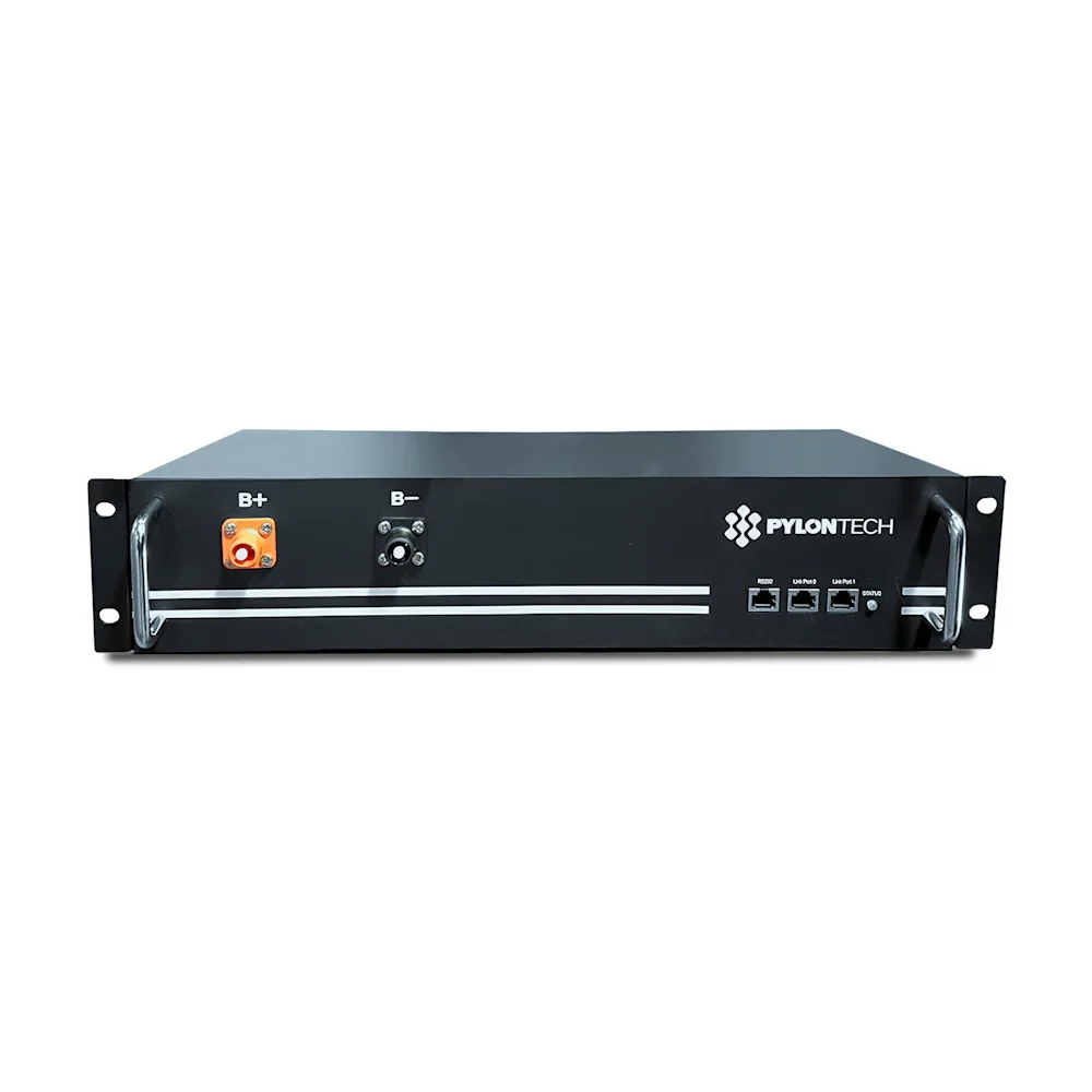
The LED indicators on the LV-HUB face-panel provide instant commissioning feedback: the binary-coded NUMBER/BIN LEDs (1–4) display the count of connected and online battery groups, making it straightforward to verify that all strings have been correctly recognised during start-up.
The LV-HUB supports both CAN Bus (500K baud, 0/120Ω terminal resistance) and RS485 (9600/115200 baud) communication standards. This dual-protocol capability ensures compatibility with the widest possible range of hybrid inverters — inverters that use CAN to read Pylontech BMS data (such as Victron, Sungrow, and Growatt) and those using RS485 (such as SMA) are both fully supported by the same hardware. The correct protocol is selected by the cable type and port used during installation.
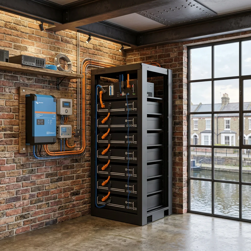
At 442 × 150 × 44 mm the LV-HUB shares the same 442 mm width as the Pylontech US-series battery modules, fitting naturally into the same 19-inch battery rack or cabinet with minimal installation effort. Its shallow 1U height means it occupies just one rack unit at the top of the stack. At 3.0–3.5 kg it is easily rack-mounted by a single installer and requires no additional mounting hardware beyond standard rack nuts and bolts.
The LV-HUB's front panel carries binary-coded LED indicators (LEDs 1–4) that display the number of battery strings currently online, plus a STATUS LED that confirms normal operation or signals an alarm in red if a string goes offline after initial commissioning. This makes it straightforward to verify that all strings are correctly connected and responding during first power-up, and to identify a failed or disconnected string quickly during maintenance.
For very large installations, up to five LV-HUBs can be interconnected in a Level 1 / Level 2 hierarchy to manage up to 200 US2000/US3000 modules (around 480 kWh). In a cascaded system, one LV-HUB is designated the Master (addressed 000001) and connects to the inverter; the remaining HUBs are addressed sequentially. All inter-HUB communication cables must be 8-pin direct-pin RJ45 cables. Each HUB draws its 48V power supply directly from the battery bus, so no separate power supply is required.
The LV-HUB draws just 2W continuously from the 48V battery bus — negligible even in off-grid systems where every watt-hour matters. It includes a dedicated ON/OFF switch on the front panel and a RESET button (press for 2 seconds to restart) for fast fault recovery without disconnecting power cables. The CAN OUT port includes a user-configurable DIP switch (position 6) for setting the 120Ω CAN bus terminal resistance — important for long cable runs where signal integrity can degrade without proper termination.
The LV-HUB is compatible with the entire Pylontech 48V residential battery range: US2000, US2000C, US3000, US3000C, UP5000, US5000, and US5000-B. Mixed-model strings are supported subject to Pylontech's model priority rules (US5000 > UP5000/US3000C/US2000C > US3000/US2000). This broad compatibility protects the investment value of the LV-HUB across system upgrades — if modules are changed or upgraded over the life of the installation, the same LV-HUB unit continues to serve as the communication backbone.
Technical Specifications
| General | |
| Manufacturer | Pylon Technologies Co., Ltd. (Pylontech) |
| Model / MPN | LV-HUB-A / LVHUBA1C0MX115R1 |
| Compatible Batteries | US2000, US2000C, US3000, US3000C, UP5000, US5000, US5000-B |
| Electrical | |
| Operating Voltage | 48 Vdc (powered from battery bus) |
| Power Consumption | 2 W |
| Communication | |
| Protocols | CAN Bus / RS485 |
| CAN Baud Rate | 500K |
| CAN Terminal Resistance | 0 Ω or 120 Ω (DIP switch selectable) |
| RS485 Baud Rate | 9,600 / 115,200 |
| CAN Protocol Version | CAN-Bus-protocol-PYLON-low-voltage-V1.2-20180408 or above |
| RS485 Protocol Version | RS485-protocol-pylon-low-voltage-V3.1-20180408 or above |
| Ports | CAN OUT, CAN IN, RS232 (debug), RJ45 ports 0–5 (battery groups), ON/OFF switch, RESET button, Dry signal (reserved) |
| System Capacity | |
| Max Strings Per LV-HUB (US5000/US3000C via CAN) | 6 strings × 16 modules = 96 modules per HUB |
| Max Strings Per LV-HUB (US2000B+ / US3000 via CAN or RS485) | 5 strings × 8 modules = 40 modules per HUB |
| Max LV-HUBs in Cascade | 5 (1 master + 4 sub, or hierarchical) |
| Max Modules (US2000/US3000, multi-HUB) | 200 modules |
| Physical | |
| Dimensions (W × D × H) | 442 × 150 × 44 mm |
| Weight | 3.0 – 3.5 kg |
| Form Factor | 19-inch rack mount (1U) |
| IP Rating | IP20 (indoor installation only) |
| Environmental & Lifetime | |
| Working Temperature | −20 °C to 60 °C |
| Storage Temperature | −40 °C to 80 °C |
| Operation Life | 15 years |
Frequently Asked Questions

Details & Craftsmanship
Every detail has been carefully considered to bring you the perfect product.
Description
The Pylontech LV-HUB (MPN: LVHUBA1C0MX115R1) is the dedicated CAN/RS485 communication hub for scaling Pylontech 48V battery systems beyond a single string. When a solar storage installation requires more battery modules than a single parallel group supports, the LV-HUB acts as the central communication controller — aggregating up to 5 separate battery strings, presenting them to the inverter as a single, unified battery system. It supports the full range of Pylontech 48V LiFePO₄ modules including the US2000, US2000C, US3000, US3000C, UP5000, and US5000 series, and carries an operational design life of 15 years in the same IP20-rated, 19-inch rack-mount format as the batteries it manages. Without the LV-HUB, parallel multi-string configurations either lose BMS communication integrity or require unsupported direct wiring between groups — making this a mandatory accessory for any large residential or commercial Pylontech BESS.
🔴 Installer Requirements
- The LV-HUB is a low-voltage DC device powered directly from the 48V battery bus. All connections to the 48V bus must be made by a competent electrician and must include a suitably rated DC protection breaker between the battery system and the inverter.
- Strict power-up sequence must be followed: connect all power cables first, verify all battery DIP switches are set to X0XX, turn on all batteries and wait for the group-1 master battery buzzer to ring three times confirming all groups are online — only then connect the LV-HUB communication cable and set the DIP switch to 000001 before powering the LV-HUB. Incorrect sequencing can cause communication errors or prevent battery groups from being recognised.
- The LV-HUB is rated IP20 — indoor installation only. Do not install in outdoor enclosures, damp locations, or environments outside the operating temperature range of −20 °C to 60 °C.
- Communication cables between battery modules and from groups to the LV-HUB must be 8-pin direct-pin RJ45 cables. Cables from a group master battery to LV-HUB ports 1–5 must have the first 3 pins NULL or use the Pylontech WI0SCAN30RJ1 cable from the external cable kit. Using incorrect cable types will prevent BMS communication.
🟠 Compatibility & When the LV-HUB Is Required
- US5000 / US5000-B / US3000C / US2000C: The LV-HUB is only required once you exceed 16 modules in a single string. A single LV-HUB supports up to 6 strings of 16 US5000/US3000C modules via CAN. RS485 multi-string connection for these models does not require a LV-HUB — refer to the individual battery manual for RS485 multi-string wiring.
- US2000B Plus / US3000: The LV-HUB is required once you exceed 8 modules in a single string. A single LV-HUB supports up to 5 strings of 8 modules via CAN or RS485.
- Multi-HUB systems: For systems requiring more than 5 strings, up to 5 LV-HUBs can be cascaded in a hierarchical arrangement, with one HUB acting as Master (Level 1). Each HUB requires a unique DIP switch address. Systems with 2–5 LV-HUBs require one additional LV-HUB to act as the Master Hub.
- SMA Sunny Island users: The ADD DIP switch on the master HUB must be set to 000011 (firmware B14V0105) or 000101 (firmware B14V0106) — different from the standard 000001 setting. Check the product label firmware version before commissioning.
- Warranty note: For warranty purposes, Pylontech classifies the LV-HUB as a component of the battery system. The battery warranty terms and conditions therefore apply to this unit.
🟢 How the LV-HUB Works in a Multi-String System
Without the LV-HUB, an inverter can only receive BMS data (state of charge, cell temperatures, alarm flags) from a single battery string. The LV-HUB solves this by acting as a communication concentrator: it collects data from all connected battery strings via CAN or RS485, aggregates it, and presents a single BMS data feed to the inverter — as if the entire bank were one battery. The inverter can then make precise charge/discharge decisions based on the overall bank status rather than a single module's data, protecting every cell in every string and maximising the usable capacity of the whole system.
The LED indicators on the LV-HUB face-panel provide instant commissioning feedback: the binary-coded NUMBER/BIN LEDs (1–4) display the count of connected and online battery groups, making it straightforward to verify that all strings have been correctly recognised during start-up.
The LV-HUB supports both CAN Bus (500K baud, 0/120Ω terminal resistance) and RS485 (9600/115200 baud) communication standards. This dual-protocol capability ensures compatibility with the widest possible range of hybrid inverters — inverters that use CAN to read Pylontech BMS data (such as Victron, Sungrow, and Growatt) and those using RS485 (such as SMA) are both fully supported by the same hardware. The correct protocol is selected by the cable type and port used during installation.
At 442 × 150 × 44 mm the LV-HUB shares the same 442 mm width as the Pylontech US-series battery modules, fitting naturally into the same 19-inch battery rack or cabinet with minimal installation effort. Its shallow 1U height means it occupies just one rack unit at the top of the stack. At 3.0–3.5 kg it is easily rack-mounted by a single installer and requires no additional mounting hardware beyond standard rack nuts and bolts.
The LV-HUB's front panel carries binary-coded LED indicators (LEDs 1–4) that display the number of battery strings currently online, plus a STATUS LED that confirms normal operation or signals an alarm in red if a string goes offline after initial commissioning. This makes it straightforward to verify that all strings are correctly connected and responding during first power-up, and to identify a failed or disconnected string quickly during maintenance.
For very large installations, up to five LV-HUBs can be interconnected in a Level 1 / Level 2 hierarchy to manage up to 200 US2000/US3000 modules (around 480 kWh). In a cascaded system, one LV-HUB is designated the Master (addressed 000001) and connects to the inverter; the remaining HUBs are addressed sequentially. All inter-HUB communication cables must be 8-pin direct-pin RJ45 cables. Each HUB draws its 48V power supply directly from the battery bus, so no separate power supply is required.
The LV-HUB draws just 2W continuously from the 48V battery bus — negligible even in off-grid systems where every watt-hour matters. It includes a dedicated ON/OFF switch on the front panel and a RESET button (press for 2 seconds to restart) for fast fault recovery without disconnecting power cables. The CAN OUT port includes a user-configurable DIP switch (position 6) for setting the 120Ω CAN bus terminal resistance — important for long cable runs where signal integrity can degrade without proper termination.
The LV-HUB is compatible with the entire Pylontech 48V residential battery range: US2000, US2000C, US3000, US3000C, UP5000, US5000, and US5000-B. Mixed-model strings are supported subject to Pylontech's model priority rules (US5000 > UP5000/US3000C/US2000C > US3000/US2000). This broad compatibility protects the investment value of the LV-HUB across system upgrades — if modules are changed or upgraded over the life of the installation, the same LV-HUB unit continues to serve as the communication backbone.
Technical Specifications
| General | |
| Manufacturer | Pylon Technologies Co., Ltd. (Pylontech) |
| Model / MPN | LV-HUB-A / LVHUBA1C0MX115R1 |
| Compatible Batteries | US2000, US2000C, US3000, US3000C, UP5000, US5000, US5000-B |
| Electrical | |
| Operating Voltage | 48 Vdc (powered from battery bus) |
| Power Consumption | 2 W |
| Communication | |
| Protocols | CAN Bus / RS485 |
| CAN Baud Rate | 500K |
| CAN Terminal Resistance | 0 Ω or 120 Ω (DIP switch selectable) |
| RS485 Baud Rate | 9,600 / 115,200 |
| CAN Protocol Version | CAN-Bus-protocol-PYLON-low-voltage-V1.2-20180408 or above |
| RS485 Protocol Version | RS485-protocol-pylon-low-voltage-V3.1-20180408 or above |
| Ports | CAN OUT, CAN IN, RS232 (debug), RJ45 ports 0–5 (battery groups), ON/OFF switch, RESET button, Dry signal (reserved) |
| System Capacity | |
| Max Strings Per LV-HUB (US5000/US3000C via CAN) | 6 strings × 16 modules = 96 modules per HUB |
| Max Strings Per LV-HUB (US2000B+ / US3000 via CAN or RS485) | 5 strings × 8 modules = 40 modules per HUB |
| Max LV-HUBs in Cascade | 5 (1 master + 4 sub, or hierarchical) |
| Max Modules (US2000/US3000, multi-HUB) | 200 modules |
| Physical | |
| Dimensions (W × D × H) | 442 × 150 × 44 mm |
| Weight | 3.0 – 3.5 kg |
| Form Factor | 19-inch rack mount (1U) |
| IP Rating | IP20 (indoor installation only) |
| Environmental & Lifetime | |
| Working Temperature | −20 °C to 60 °C |
| Storage Temperature | −40 °C to 80 °C |
| Operation Life | 15 years |
Frequently Asked Questions